
Optical Table System Design
Optical Table System Design
Optical Table System Design
In optical tables, "noise" refers to three types of vibration: seismic, acoustic, and tabletop forces. Seismic vibrations come from the ground underneath the table and can be caused by foot and vehicle traffic, wind, and building vibrations. Acoustic noise comes from sound waves that travel through the air and walls. Tabletop forces are caused by vibrations on the working surface, such as a moving positioning stage or vacuum-system tubing. The term optical table system typically refers to a vibration-isolation system, that is, the tabletop plus the support system (see Figure 1). Such tables generally come in several grades, determined by the level of vibration damping they provide. Basic optical tables for general-purpose use are suitable for quiet environments and provide little or no vibration damping mechanisms, but because of their honeycomb composite construction, they provide a rigid platform for general optical experiments that are relatively insensitive to vibration such as spectroscopy, velocimetry, and non-phase-dependent applications. An intermediate-grade table typically incorporates broadband damping or a moderate level of tuned mass dampers to reduce the compliance of the table to disturbances. It is typically preferred for experiments like bioimaging, Raman spectroscopy, micropositioning, and machining. For more demanding applications like interferometery, nanopositioning, and imaging, or for labs with excessive vibration and acoustic noise, a higher-performance table should be used that provides the maximum damping and consequently the quietest table surface for the application. Tables in this category incorporate more tuned mass dampers or active dampers. The various components that make up such vibration control systems are the subjects of this section.
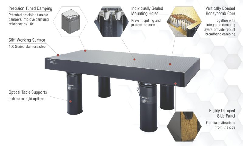
Figure 1. A vibration-isolation system which includes an optical table and the support system.
Optical Table Design
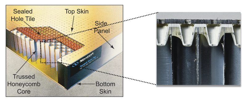
Figure 2. Depiction of an optical table revealing the internal honeycomb core construction (left). Cross-sectional view of the top portion of an optical table (right).
Optical tables provide a rigid platform for high-precision optical experiments and systems. They are designed to eliminate errors caused by relative motion between optical components in the beam path. Rigidity is the primary consideration in optical table design. Table rigidity can be quantified in terms of static or dynamic rigidity. Static rigidity describes the ability of an optical table to resist deflection when the static or quasi-static load distribution is changed. It defines the table performance when stages move across the table or equipment is relocated, added, or removed. Dynamic rigidity describes the ability of an optical table to resist deflection in response to mechanical excitation. It describes the table performance in response to floor vibration, acoustic noise, and mechanical sources on top of the table. A honeycomb design is commonly used to produce very low weight, highly rigid structures. Reduced weight dramatically improves the dynamic rigidity of the structure by moving structural resonance modes to higher, less detrimental frequencies. The structural resonance modes are the frequencies at which the platform deflects, thus causing relative motion across the optics mounting surface. For a given input vibration force, the deflection will be reduced as the mode frequency increases. This is the primary reason why steel honeycomb (see Figure 2) has replaced granite in most high-end optical applications. Since granite is relatively heavy, the resonance modes occur at lower frequencies and therefore, produce higher amplitudes of surface deflection. There are additional improvements that can increase the efficacy of the honeycomb design. A trussed core design uses an additional steel member to bridge across the center of the honeycomb cell. This extra mechanical component significantly stiffens the cell with very little increase in weight, resulting in improved static and dynamic rigidity. By vertically bonding along the height of the honeycomb core, the table's rigidity-to-weight ratio can be maximized. The trussed core design possesses a triple core interface at each honeycomb cell. By bonding the three sheets over the full table height, greater stiffness is produced.
Disturbances caused by relative motion between optical components generally occur at the structurally dominant bending or torsional modes. In addition to pushing these natural modes to higher, less detrimental frequencies, a major advantage of honeycomb over granite is the high level of damping present in the honeycomb structure. Damping attenuates the amplitude of the natural modes and reduces the relative motion across the table surface. Generally, the two types of passive damping used for optical tables include narrowband tuned damping and broadband damping. Tuned damping techniques use individual mode selected vibration absorbers to both eliminate a particular "narrow" mode and mode harmonics across the broader band. On the other hand, broadband damping techniques indiscriminately absorb moderate amounts of vibration over the broadband. Narrowband tuned damping is the most effective means for eliminating structural resonances, which can be seen by comparing their respective compliance curves in Figure 3. These narrowband dampers selectively cancel vibration modes to minimize the dynamic deflection coefficient and make the table behave more like an ideal rigid structure. While some narrowband damper designs use oil, others use a mass-spring mechanism, which can improve performance and allow for tuning to the exact frequency needed to damp the resonance. While broadband damping is less effective than narrowband techniques, it can still improve table performance. One method for broadband damping involves the use of constrained layer structures, which usually consist of two or more metallic sheets separated by a compliant material. For instance, the three metallic sheets in the trussed honeycomb core are each separated by an adhesive. Although the adhesive is rigid, its damping factor is much higher than that of steel and introduces substantial damping into the core. Other broadband damping techniques include introducing a polymeric material that serves to seal the honeycomb core and dampen the working surface. The polymer experiences the same bending and shear stresses as the stainless steel top but, since the damping factor of this material is much higher than that of steel, considerable damping is introduced into the work surface. Damped table sides can also improve vibration sensitivity. In this case, the sides of the table are made of a highly damped, epoxy sealed wood composite. Compared to metal sides, the composite wood sides offer significant damping to the structure and eliminate another source of resonance.
Passive and Active Damping
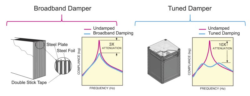
Figure 3. Broadband damper technology and corresponding compliance curve illustrating moderate damping over a wide range of frequencies (left). Tuned damper technology and associated compliance curve showing concentrated damping at the frequencies of dominant resonance modes (right).
Tuned narrowband dampers are effective at suppressing flexural resonance vibration of the table. However, these dampers are typically tuned to the table's particular resonant frequencies and cannot be adjusted for significant changes to table loading (which also change the resonances). Methods of active vibration control can provide high efficiency without the restrictions of passive methods. Active vibration control involves monitoring vibrations of a structure and utilizing the vibration signal to generate a force with the proper phase and amplitude to attenuate the vibration. An additional advantage of an active approach is the ability to supply a vibration signal that can be used independently for monitoring the vibration environment. Two sensor-actuator assemblies are typically integrated into the structure of the optical table at two corners. The design ensures rigid coupling of the sensor and the actuator, and includes a stiff tubular structure coupling the damper to both top and bottom facesheets. The damping performance is on par with that of high-quality passive tuned absorbers. However, if the table is loaded by a weight comparable to the weight of the table, the passive vibration absorbers can become "mistuned", whereas an active damper will work equally well after re-tuning.
Pneumatic isolators filter vibration before the mechanical noise can reach the optical bench work surface. Improved vibration isolation reduces errors caused by relative motion between optical components in the beam path. Pneumatic isolators combine with the optical table and payload to form a mass/spring/damper system. Pneumatic systems are used instead of mechanical springs since they offer self-leveling and minimize the effect of varying mass on isolation. Conventional isolators use a compliance chamber to act as an air spring and a damping chamber to increase system stability (see Figure 4). The compliance chamber is sealed with a flexible diaphragm to form a piston and support the optical table on compressed air. If the piston is pushed further into the compliance chamber, the pressure of the gas increases and provides a restoring force - somewhat like a soft spring. The isolation performance is primarily related to the volume of the compliance chamber. After the compliance chamber, air is pumped to the damping chamber through a flow restricter - usually a thin tube or orifice. The restricter dissipates energy in the air and essentially damps the system. The design of both chambers and the restricter must be optimized to minimize the natural frequency/damping trade-off. The performance of the isolator is defined primarily by its natural frequency and damping characteristics as summarized in the transmissibility plot in Figure 4. The pneumatic isolator is essentially a simple harmonic oscillator that uses the "fast roll-off" at higher frequencies to act as a low pass mechanical filter. Below the natural frequency of the harmonic oscillator, the isolator is essentially rigid and vibration is passed directly to the platform. At the natural frequency, vibration is actually amplified. Therefore, a primary goal is to lower the natural frequency since this improves low frequency isolation and overall isolation bandwidth. Another primary goal is to damp the harmonic oscillator amplitude at resonance. This lowers the magnification of vibration at low frequencies and improves system stability. Unfortunately, there is a compromise between the natural frequency and damping. As damping is increased, the isolator natural frequency moves slightly higher, and higher frequency isolation is decreased.
Isolation
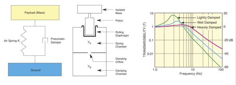
Figure 4. Depiction of a pneumatic isolator with damping (left) and a typical transmissibility plot showing damping effects (right).