Thermopile Sensor Physics
Thermopile Sensor Physics
Thermopile Sensor Physics
Thermocouples
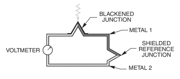
Radiation detecting thermopiles are based on thermocouples. A thermocouple consists of two dissimilar metals connected in series. To detect radiation, one junction is blackened to absorb the radiation. The temperature rise of the junction (with respect to another non-irradiated junction) generates a voltage. This effect, discovered by Seebeck, is the basis of all thermocouple temperature sensors.
The thermocouple materials are usually bismuth and antimony, which have a relatively high thermoelectric coefficient. Even with these materials, amplifier noise limits the detectivity because of the relatively low output voltage.

Thermopile Optical Power Sensors
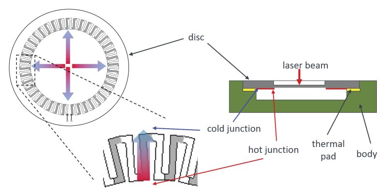
Thermopile sensors are based on thermocouples. A thermocouple consists of two dissimilar metals connected in series. To detect radiation, one metal junction is typically blackened to absorb the radiation. The temperature rise of this junction with respect to another non-irradiated junction generates a voltage. This effect is the basis of all thermocouple temperature sensors. The thermocouple materials used in thermopiles are usually bismuth and antimony, which have a relatively high thermoelectric coefficient (a measure of the magnitude of the induced voltage in response to the temperature difference). An individual thermocouple typically produces a low output voltage, which results in a low detectivity and limits its use as a sensing device. So, one way to increase the output voltage is to connect many thermocouple junctions (typically 20 to 120) in series. All the "hot" junctions are placed close together to collect the radiation. This constitutes a thermopile. The typical operation of a thermopile is shown in Figure 2.

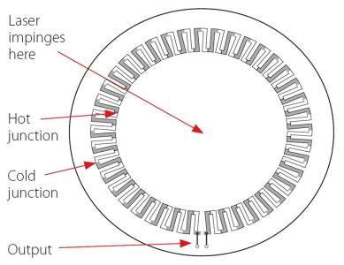
The thermopile disc consists of a circular array of thermocouples. The optical radiation, e.g., laser beam, is absorbed by the disc generating the output voltage. The heat on the disc spreads radially across the thermopile on the reverse side of the disc where it is transferred to a heat sink that is convectively cooled by a fan or by water. These devices are quite sensitive in the IR due to their broadband absorption. Consequently, care must be taken to stabilize their field of view, since all near room-temperature objects, including people, emit significant IR. Due to the heating and cooling processes, the response time of a thermopile is quite slow, typically on the order of seconds. Due to this time constraint, thermopiles are used exclusively for measuring the power of CW or quasi-CW radiation sources. The response time can be shortened by proportionally reducing the thermal capacity of the material. However, the detectivity of the detector is inversely proportional to the heat capacity, resulting in a general tradeoff between temporal response and sensitivity.
Since all the heat absorbed flows through the thermocouples (as long as the laser beam is inside the inner circle of hot junctions), the response of the detector is almost independent of beam size and position. If the beam is close to the edge of the inner circle, some thermocouples become hotter than others but since the sum of all of them is measured, the reading remains the same. Generally, we specify ±2% uniformity of reading over the surface or better.
Using Thermopile Sensors to Measure Single Shot Energy
Although thermopile laser power sensors are used primarily to measure power, they can also measure single shot energy, where they integrate the power flowing through the disc over time. Since the typical time it takes for the disc to heat up and cool down is several seconds, these thermal sensors can only measure one pulse every several seconds at most. Thus they are suitable for what is called “single shot” measurement. Although the response time of the sensor discs is slow, there is no limit to how short the pulses measured are since the measurement is of the heat flowing through the disc after the pulse.
Types of Thermopile Discs
There is no single absorber which meets the needs of all laser power measurement applications. Several types of absorbers are available for different applications, such as long pulses (0.1-10ms), short pulses (<1µs) and continuous radiation. Absorbers optimized for long pulses and CW are characterized by thin, refractory materials, since the heat can flow through the coating and into the disc during the pulse. On the other hand, heat cannot flow during short pulses, and all the energy is deposited in a thin (typically 0.1µm) layer near the surface. This causes vaporization of the surface which ruins the absorber. Instead, a volume absorber that is partially transparent and absorbs over a distance of 50 µm -3 mm is used. This spreads the heat over a larger volume allowing much higher energies.
Thermopiles can measure from tens of microwatts to Kilowatts. Nevertheless, the thermal range of operation of the discs is limited. If the difference between the hot and cold junction temperature exceeds tens of degrees, the constant heating/cooling of the junctions can cause premature failure in the junctions. In order to accommodate different power ranges, discs of different thicknesses and sizes are used, thick ones for high powers and thin ones for low powers.
The response time of the discs is dependent on their size and shape: larger diameters and thicker discs are slower than thin small diameter ones. The response time is in general dependent on the mass of material which has to heat up in the thin absorber region of the disc vs. the speed the heat flows out of the same region. The response time is approximately proportional to the aperture, i.e. a 50mm aperture disc is three times as slow as an 18mm aperture disc.
Thermal Surface Absorbing Heads
A surface absorber typically consists of an optically absorbing refractory material deposited on a heat conducting substrate of copper or aluminum. When a long pulse of several hundred µs or a continuous laser beam falls on such a surface absorber, the light is absorbed in a very thin layer of the surface – typically 0.1 – 1 µm thickness. Although the light is absorbed in a thin layer and there converted into heat, the pulse is long enough so that while energy is being deposited into the surface layer, heat is also flowing out into the heat conducting substrate and therefore the surface does not heat up excessively.
Surface vs. Volume Absorbers
When measuring a laser with short pulses of tens of µs or less, the heat is deposited in a short time and cannot flow during the pulse. Therefore a surface absorber which absorbs the energy in a thin surface layer is not suitable. All the energy is deposited in a thin layer and that layer is vaporized. In this case, volume absorbers are used. These have traditionally consisted of a neutral density glass thermally bonded to a heat-conducting metallic substrate. The ND glass absorbs the light over a depth of 1-3 mm instead of fractions of a micrometer. Consequently, even with short pulses where there is no heat flow, the light and heat are deposited into a considerable depth of material and therefore the power/energy meter with a volume absorber is able to withstand much higher energy densities – up to 10 Joules/cm2

Related Topics
Optical Sensors
Beam Characterization
