
Critical Laser Components
Critical Laser Components
Critical Laser Components
Required Components for Lasing
The critical components of a laser are a gain medium, a pump source, and a resonator. Table 1 lists the primary functions of these components as well as typical examples while Figure 1 illustrates these components in an operational laser.
| Component | Function | Examples |
|---|---|---|
| Gain Medium | Acts as medium for population inversion Determines laser emission properties |
Atomic or molecular gases (Ne, Ar, CO2) Ions in crystals or glasses (Nd, Er, Yb, Cr) Semiconductors (GaAs, InGaAsP) |
| Pump Source | Serves as energy source for inverting population | Electric discharge Flashlamp or arc lamp Other laser Electric current |
| Resonator | Provides feedback mechanism for amplification Selects spectral and spatial properties of light |
Bulk mirrors in solid-state laser Cleaved or coated facets in laser diode Bragg reflectors in fiber laser |
Table 1. Function and examples for the three components of lasers.
Gain Medium
Gain in a laser medium can be described by considering two energy levels with population densities, N2 and N1 and an associated transition cross section σ21, as described by the below equation. Since population exists in both levels, absorption and stimulated emission will occur within the medium. If I0 is the intensity of a beam (See Characteristics of Laser Output) before entering a material that has a length L, the light intensity I exiting the material is given by:
Based on Light-Matter Interactions in Lasers, if N1 is greater than N2, absorption is the dominant process and the exponent in the above equation is negative, resulting in attenuation of the beam. In this case, the product of the population difference (ΔN) and the cross section (σ21) is known as the absorption coefficient (α), a measure of the loss in intensity per unit length. Conversely, if N2 exceeds N1, a population inversion exists and stimulated emission will dominate over absorption. The equation then possesses a positive exponent, giving rise to amplification. The product σ21ΔN is then defined as the gain coefficient (G) representing the gain per unit length. In order to maximize the amplification, a laser gain medium should possess a large transition cross section at the wavelength of interest and be able to support a significant population inversion.
In practice, more than two energy levels are necessary to achieve a population inversion because a two-level scheme allows, at best, only equal populations of the upper and lower levels, thereby leading to no amplification. Alternatively, three- and four-level laser systems (as shown in Figure 2) essentially decouple the upper and lower levels. A three-level system pumps population from the ground state (level 1) into an excited state (level 3) which, rapidly decays to the level from which stimulated emission occurs (level 2). Level 2 is often referred to as the metastable level since it has a long lifetime. The lower level, where stimulated emission terminates (level 1), should be de-pumped rapidly to dispose of its population. These two requirements, i.e., long lifetime for upper level and short lifetime for lower level, help guarantee that a reasonably large population inversion can be maintained. Since level 1 is also the ground state, it possesses an inherently large population. Therefore, substantial pumping must be implemented to ensure that more than half of the atoms reach the metastable level 2. These disadvantages of a three-level system are avoided in a four-level system. Here, level 1 is situated above the ground state (level 0). Typically, rapid non-radiative decay depopulates this level, making a population inversion easier to achieve. State-level diagrams for a variety of laser media are given in Types of Lasers. Population densities also change dynamically depending on a variety of processes, including radiative and non-radiative decay pathways, pumping rates, as well as absorption and stimulated emission rates. Depictions of practical three- and four-level laser systems along with their decay pathways are shown in Figure 2.
Pump Source
A variety of different pumping mechanisms are used to achieve population inversions and these are typically dictated by the gain medium. Specific lasers and their associated media are discussed in Types of Lasers. In all cases, the goal is to achieve pumping rates, i.e., atoms per unit time per unit volume being raised to a metastable level, sufficient for establishing sustainable stimulated emission. For gas lasers, the pump mechanism is typically via electric discharge where an electrical current is generated in a low-pressure gas. The electrons transfer their energy to atoms via collision and promote these atoms to higher energy levels. In semiconductor lasers, electrical pumping gives rise to charge carriers within a junction that provides the upper laser level population. Details of this process is given in Optical Emission in Semiconductor Materials.
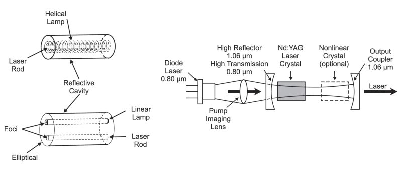
Optical pumping is the most common mechanism for generating a population inversion in solid-state lasers and this is enabled using either a lamp or a separate laser. Flashlamps or arc lamps produce intense light emission and typically have a broad emission spectrum of wavelengths that can be matched to the absorption bands of the laser medium. To efficiently pump the laser medium, the flashlamp geometry can take on different configurations, including a helix wrapped around a laser rod or laser rods inserted into an elliptically-shaped or circularly-shaped elongated laser cavity (see Figure 3). Laser pumping is used when the pumping energy must be concentrated into a relatively small volume, delivered over a short period, or provided over a narrow bandwidth. Pumping via semiconductor lasers has several advantages, including increased system efficiency, better light coupling into the laser medium, and compact geometry. Figure 3 shows a typical end-pumping configuration for a semiconductor laser diode; however, other geometries such as side-pumping and close-coupling configurations also exist. When a laser diode pumps a solid-state gain medium, it is referred to as a diode pumped solid-state (DPSS) laser system. DPSS lasers can be used to generate very large pumping rates for other solid-state lasers.
Resonator
In a laser, the gain medium is placed inside an optical resonator that provides feedback. This feedback mechanism allows for photons generated by stimulated emission to be reflected back into the laser medium for further amplification. A common example of a laser resonator or cavity uses two mirrors separated by a specific distance (d) (see Figure 1). Typically, one mirror (known as the end mirror) is highly reflective at the lasing wavelength, while the other mirror (known as the output coupler) is partially transmissive so that a portion of the light exits the cavity as the laser beam. One benefit of this feedback mechanism can be gleaned from light intensity equation, which gives the optical gain in a laser as the product of the gain coefficient and the laser medium length (GL). For a given laser gain medium, extending L could be a means to generate sufficient gain for lasing but there are clearly practical limitations to simply elongating the gain medium.
An increase in the effective optical pathlength can provide a means for enhancing gain. This can be achieved by placing the laser medium inside an optical resonator. This is illustrated when comparing the upper two graphics in Figure 4, which show a gain medium with and without a resonator. While the additional passes allow for increased gain when compared to a single pass geometry, after just a few passes through the gain medium, the light begins to leak outside the cavity. For this optical feedback to work efficiently, the resonator must be designed to be stable such that light stays inside the cavity and do not leak out. The parallelism of the mirrors, as well as their curvatures, play a large role in the design of stable laser resonators. The lower part of Figure 4 shows a few typical resonator configurations while detailed discussions of resonators and their stability regimes can be found in. In addition to the resonator-induced feedback leading to increased gain, it also decreases the beam divergence significantly (see upper portion of Figure 4). This decreased beam divergence is responsible for the high degree of collimation observed for most laser beams (see Characteristics of Laser Output for more details).
Since an amplifier with positive feedback is an oscillator, a laser is often called an optical oscillator. For laser oscillation or lasing to occur, two conditions must be satisfied that are governed by the gain medium and the resonator. The first condition dictates that the optical gain GL be greater than the total losses (αr) for a single round trip through the cavity. Parasitic losses within a laser cavity typically come from absorption within the gain medium itself, optical scattering or absorption from any element within the cavity. Necessary losses, such as those associated with transmission through the output coupler, must also be considered. The second condition requires that light waves within the resonator must coherently add or constructively interfere with one another(see Characteristics of Laser Output on coherence for details). Only light that possesses an integral number of oscillating waves that fit within the cavity length (d) will be supported. These standing waves are known as resonator modes and are depicted in Figure 5. Longitudinal modes differ from one another only in their oscillation frequency with a separation (Δν) given by:
This frequency separation is typically small (~ 0.5 GHz) compared to the laser gain bandwidth and any longitudinal mode that has sufficient gain can undergo lasing. There can be a single longitudinal mode or several hundred thousand modes depending on the gain bandwidth. On the other hand, transverse modes follow different transverse paths through the amplifier and therefore emerge larger in size and in divergence. Figure 5 shows a variety of laser beam intensity distributions associated with different cylindrical transverse modes. These are defined by their transverse electromagnetic (TEMmn) distributions with the lowest order mode being the TEM00, which is discussed further in Laser Beam Spatial Profiles.
Based on this discussion a laser can be considered a resonant optical amplifier whose output is fed back to the input with matching phase.
Related Topics
Lasers