Deep UV Photolithography
Deep UV Photolithography
Deep UV Photolithography

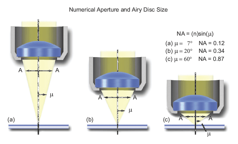
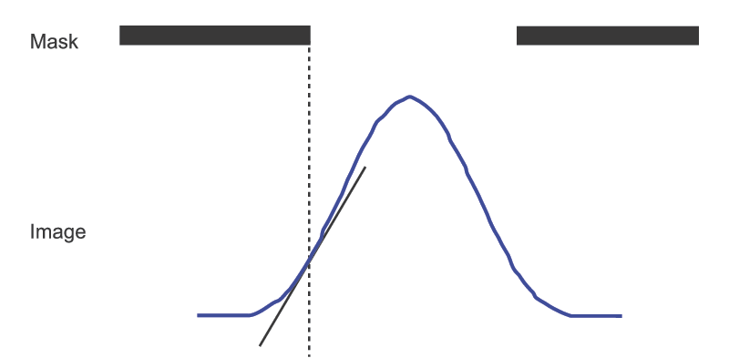

These rules highlight the key parameters that have been adjusted as photolithography technology has progressed to smaller and smaller feature sizes. The Rayleigh equation shows that, to reduce the feature size, one must either reduce the wavelength of the exposing light or increase the NA of the projection optics. The DOF must be sufficient to ensure accuracy and precision in the feature size through the entire thickness of a resist. Simplistically, the feature size that is achievable in a lithography process depends on the Rayleigh equation, while the process yield is dependent on the projection system's DOF.
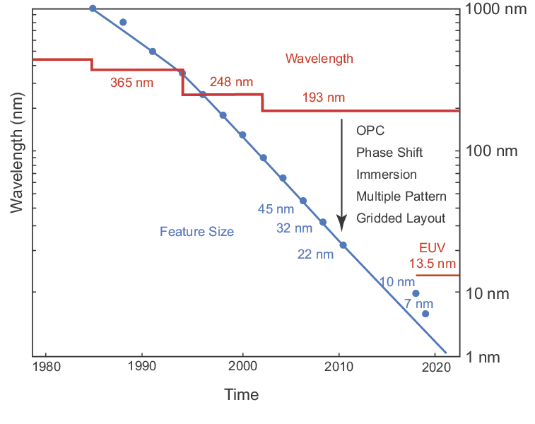
Figure 4 shows the historical progression of IC feature sizes and the wavelength of the photolithography light source required to achieve these feature sizes. Until recently, photolithography equipment designers have focused primarily on wavelength reduction to achieve smaller feature sizes:
- Arc lamp systems developed in the 1970's and early 1980's (λ = 436 nm) are useful down to feature sizes of about 450 nm
- Mercury lamp I-line systems developed in the mid-1980's (λ = 365 nm) are useful down to feature sizes of about 380 nm
- KrF excimer laser-based systems developed in the 1990's (λ = 248 nm) are useful down to feature sizes of about 250 nm
- ArF excimer laser-based systems (λ = 193 nm) are useful down to feature sizes of about 65 nm
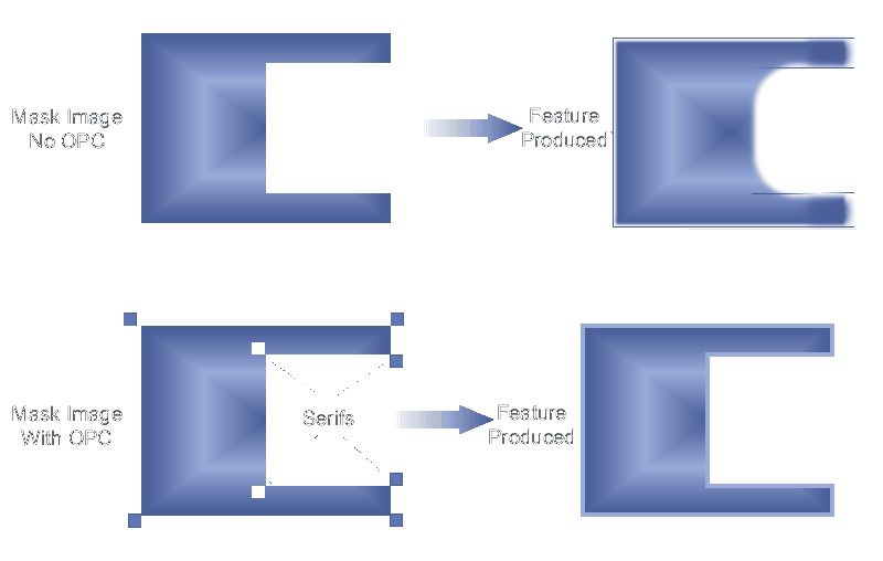
OPC techniques compensate for image distortions that occur when printing feature sizes smaller than the wavelength of the exposing light. Typically, these distortions result in shortening of line ends, corner rounding or changes to linewidths. OPC corrections are made at the mask level and involve changes to the mask image such as the addition of serifs at design corners and augmentation to linewidths. Figure 5 shows a simple example of how OPC corrections are made at the mask level.
